hile creating the OBD2 reader application, we faced many questions, problems, and so on, so we will try to acquaint you with them in this article. As it turned out, you can conduct a dialogue with the car, and quite a productive one. However, in order to start communicating with the car, it is necessary to "establish contact", "ask the right question" and correctly understand the "answer" received from the car. Accordingly, the article will be aimed at clearly explaining the organization of the dialogue, as well as telling you what mistakes you may encounter on the way and how to deal with them.
Connection selection
Initially, it is necessary to clarify that an ELM327 adapter will be used to connect to the car. ELM327 is a microcircuit that allows converting the protocols used in the diagnostic tires of cars into the RS232 protocol, which we will use for data transmission. Due to the fact that data transmission via the RS232 protocol is carried out sequentially, the problem of low data transfer rate arises, which we will try to bypass in one of the following sections.
There are several variations of the ELM327 adapter, which are classified according to the data transfer method - Bluetooth, WIFI, USB. Based on the fact that the development goal is a mobile device under the Android operating system, you can choose the two most suitable versions of ELM327, such as Bluetooth and WIFI. Since there is only one method of receiving and processing data, and they differ only in the options for connecting to the adapter, you can choose only one, organize a dialogue with it, and then add the rest of the connection options.
ELM327 1.5 vs ELM327 2.1
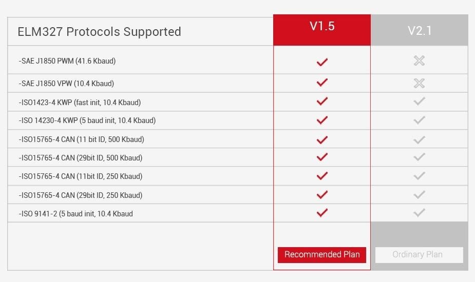
One of the first tasks that you can face was the problem of choosing the adapter itself, in our case with Bluetooth support. It turns out that if you want to support all (at least most) cars, you must choose version v1.5 instead of v2.1. In fact, you need to clarify this several times when buying an adapter, because some sellers make mistakes in the version description, because the versions are not much different. In fact, v2.1 lacks support for the J1850 PWM and J1850 VPW protocols, which means that you will not be able to connect to cars that use these protocols.
Connection
Connection to the adapter takes place in several stages:
- Adapter connection (Bluetooth, WIFI)
- Sending initialization commands (initialization string)
With the organization of the connection in general, everything is clear. The principle of operation is the same as for any Bluetooth / WIFI chat. In order to understand how to send an initialization string, you need to study what commands exist, as well as what functions they perform.
AT Z [reset all]
Reset adapter settings to factory state
AT L1-0
Enable / Disable line feed characters
AT E1-0
Echo on – off
AT H1-0
Headers on – off
AT AT0-1-2
Adaptive Timing Off — adaptive Timing Auto1 — adaptive Timing Auto2
AT ST FF
Set the timeout to max value.
AT D [set all to Default]
Reset settings to the original user-configured state.
AT DP [Describe the current Protocol]
The scanner is able to independently determine the vehicle protocol to which it is connected.
AT IB10 [set the ISO Baud rate to 10400]
The command sets the baud rate for ISO 9141-2 and
ISO 14230-4 10400
AT IB96 [ set the ISO Baud rate to 9600]
The command sets the baud rate for ISO 9141-2 and
ISO 14230-4 9600 for protocols 3,4,5.
AT SP h [ Set Protocol h]
Protocol selection command h, where h is:
0 – Automatic;
1 — SAE J1850 PWM (41.6 Kbaud);
2 — SAE J1850 VPW (10.4 Kbaud);
3 — ISO 9141-2 (5 baud init, 10.4 Kbaud);
4 — ISO 14230-4 KWP (5 baud init, 10.4 Kbaud);
5 — ISO 14230-4 KWP (fast init, 10.4 Kbaud);
6 — ISO 15765-4 CAN (11 bit ID, 500 Kbaud);
7 — ISO 15765-4 CAN (29 bit ID, 500 Kbaud);
8 — ISO 15765-4 CAN (11 bit ID, 250 Kbaud);
9 — ISO 15765-4 CAN (29 bit ID, 250 Kbaud);
AT SP Ah [Set Protocol h with Auto]
The command sets the h protocol by default, if the h connection fails, then the adapter starts automatic selection of the protocol.
Based on the commands described above, we form an initialization string.
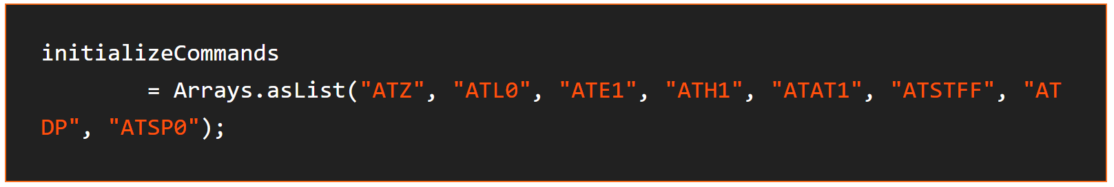
It is desirable to enable the user to change the initialization commands because, in order to find the "key" for some cars, it is necessary to choose more specific adapter settings. In our case, the settings are used that are suitable for most standard protocols.
It is also desirable to pay attention to the APSP0 command, so we set the automatic selection of the protocol by default, and this may take some time.
Accordingly, if the user knows what protocol his car has, he can change 0 to his protocol number using the ability to change the connection protocol
How Does Elm327 Work?
Reading diagnostic data
To read diagnostic data, special PID's commands are used.
PID’s (On-board diagnostics Parameter IDs) - codes that are used to query the values of indicators of certain vehicle sensors.
Basic pids can be found on Wikipedia, which contains a complete set of basic commands that all cars should support. There are also sets of commands for certain brands and types of cars, these sets are available for a fee. In our case, the application is focused on basic car diagnostics, so we use a basic set of commands.
It is also possible to receive the current data from the car, while the command for receiving data from the car will initially have 01, indicating that we want to receive real data. If we want to get the saved data of the car, then at the beginning of the command it is necessary to specify 02. For example, the command to get the current speed of the car is 010D, and to get the stored speed - 020D.
If you look closely at the number of commands that are provided by open resources, then you can just notice the problem that I wrote about at the very beginning, that is, the problem of the low response speed of the adapter. Since the sending and receiving of commands goes sequentially, in order to receive the sensor readings at a given time, you need to wait for a response to all previous commands. Accordingly, if you request to receive all commands, then there is a high probability that the update of real data will be very slow. But even this problem can be solved by displaying only those commands that exist in the car. For example:
0100 – PIDs supported [01 — 20]
0120 – PIDs supported [21 — 40]
0140 – PIDs supported [41 — 60]
0160 – PIDs supported [61 — 80]
0180 – PIDs supported [81 – A0]
01A0 – PIDs supported [A1 — C0]
I will demonstrate how to determine which sensors are present in the car using one of the pids. For example:
- 0100 \\ request
- BB1E3211 \\ response from the car
We translate the answer from the car into a binary number system

Using the following table, we can determine which pids are supported by our car, starting from 01 to 20:
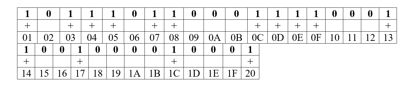
Based on the resulting data, we can determine that our car supports the following pids:

Now, instead of sending all 32 commands and waiting for a response to them, despite the fact that some of them may be missing, we will use only 15 commands. However, this is not the end of the so-called optimization. In order for the data to be updated even faster, I advise you to request only data about those sensors that are displayed on the screen. Although this limits some of the functionality of the application. For example, history recording.
Take a look at our featured case study: CarZis - Building a Mobile Application for Car Scanning with OBD II/ELM327 Integration.
Reading and decoding vehicle errors
Vehicle errors can also be different and there are specific commands for them. For example:
- 03 – To display stored error codes
- 0A –To display permanent error codes.
As with other commands, vehicle errors come in encoded form, respectively, as in other commands, they need to be decoded to get the necessary information. I will give an example of how error decoding works. The code:
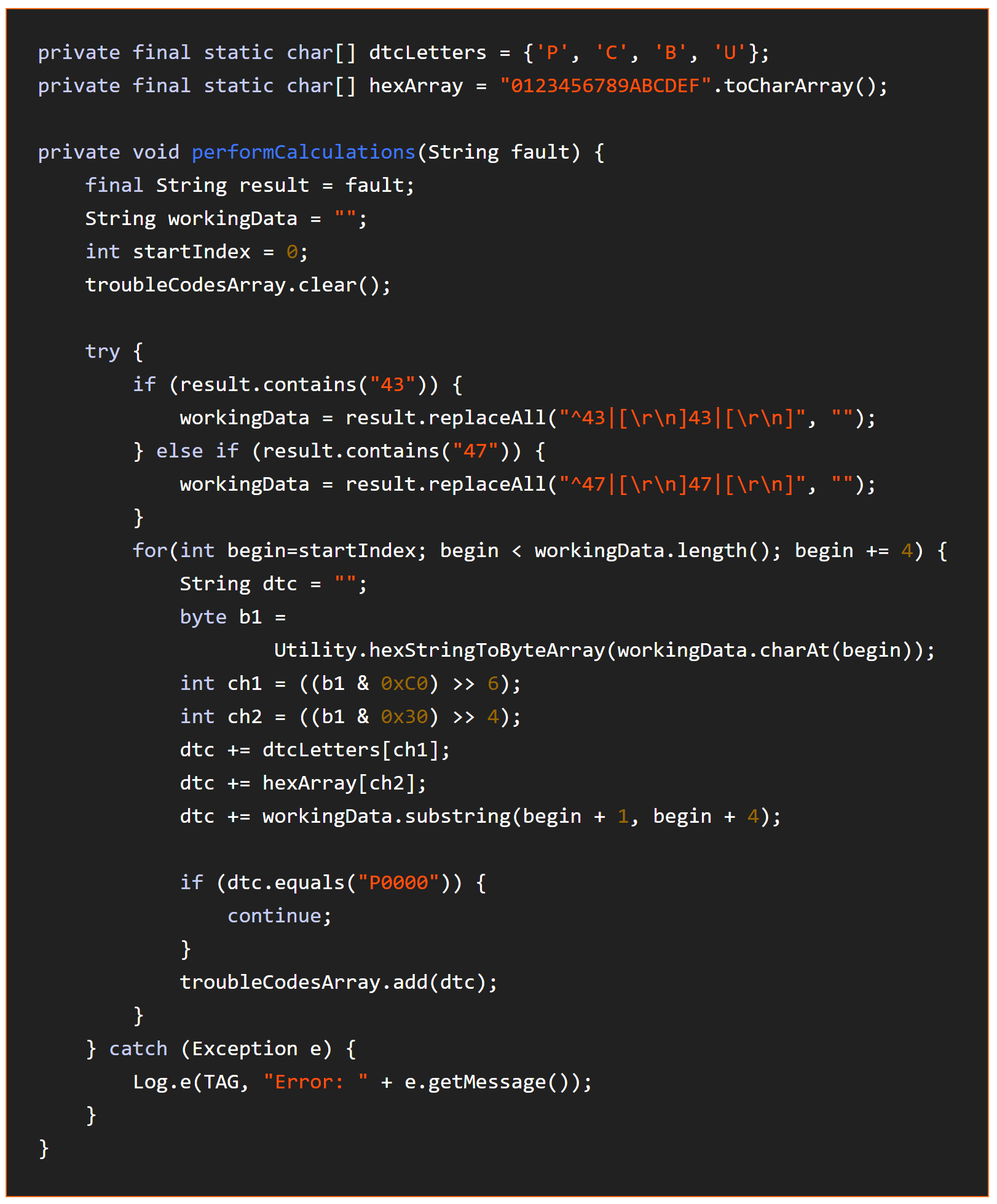
And now an explanation.
Based on the received response, we can get an error code. To do this, we decode the received message using the following tables.
First character:
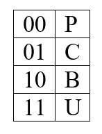
Second character:
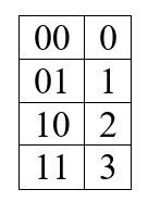
3, 4, 5 characters are formed according to this table:
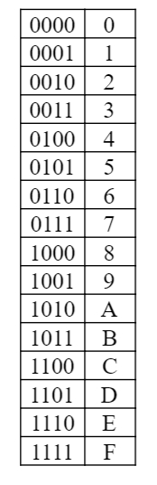
Based on this, we can try to parse the following answer:
0001000000111110
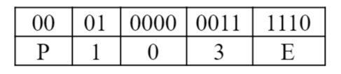
Error code: P103E
Epilogue
At this stage, we figured out how to organize a dialogue with the adapter, send commands to it, receive and decrypt its responses. This is the bulk of the job, considering how much time it takes to study the documentation, but at the same time it is quite interesting. Outside of the discussion of this article, there are many problems associated with the visual interface, as well as many additional functions, such as adding new pids from a file, a standard and advanced way of connecting to the adapter, and plotting graphs.
